Category: Tech

  • Understanding Operational Amplifiers: The Basics and Beyond

    Understanding Operational Amplifiers: The Basics and Beyond


    Operational amplifiers, or op-amps for short, are widely used electronic components that play a crucial role in many circuits and devices. In this article, we will take a closer look at op-amps, starting with their definition and function, and moving on to explore their many applications, configurations, characteristics, and design considerations.

    Definition and Function

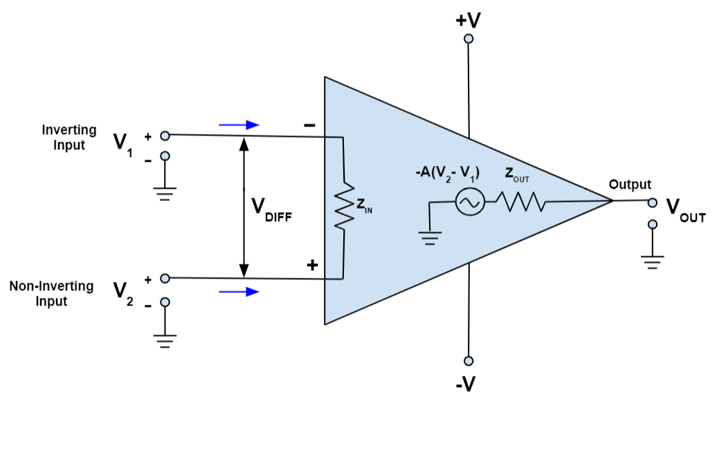
    An operational amplifier is a high-gain voltage amplifier that has two input terminals (one inverting and one non-inverting) and one output terminal. It is typically used to amplify, filter, or process signals in analog circuits. The op-amp is called an “operational” amplifier because it can perform a variety of mathematical operations on its input signals, such as addition, subtraction, differentiation, and integration.

    Applications in Electronics

    Op-amps are used in a wide range of electronic devices and systems, including audio amplifiers, voltage regulators, power supplies, oscillators, filters, comparators, and many others. They are also used in instrumentation and control systems, where their high accuracy and stability are essential.

    Operational Amplifier Configurations

    There are several common configurations of op-amps, including inverting amplifiers, non-inverting amplifiers, summing amplifiers, difference amplifiers, integrators, and differentiators. Each configuration has its own unique characteristics and applications.

    Inverting Amplifier: This configuration amplifies the input signal and produces an inverted output signal. It is widely used in audio amplifiers and other applications where the phase of the signal is not critical.

    Non-Inverting Amplifier: This configuration amplifies the input signal and produces a non-inverted output signal. It is commonly used in applications where the phase of the signal needs to be preserved.

    Summing Amplifier: This configuration adds together multiple input signals and produces a single output signal. It is used in applications such as audio mixers and signal processing.

    Difference Amplifier: This configuration amplifies the difference between two input signals and produces a single output signal. It is used in applications such as instrumentation and control systems.

    Integrator: This configuration produces an output signal that is proportional to the integral of the input signal. It is used in applications such as signal processing and waveform generation.

    Differentiator: This configuration produces an output signal that is proportional to the derivative of the input signal. It is used in applications such as signal processing and waveform analysis.

    Operational Amplifier Characteristics

    Op-amps have several important characteristics that affect their performance and application, including gain and bandwidth, input and output impedance, slew rate, and noise. Understanding these characteristics is essential for choosing and designing op-amp circuits.

    Gain and Bandwidth: Op-amps have a high gain, which is the ratio of output voltage to the input voltage. They also have a limited bandwidth, which is the range of frequencies over which they can amplify signals effectively.

    Input and Output Impedance: Op-amps have a high input impedance, which means that they draw very little current from the input signal source. They also have a low output impedance, which means that they can drive a high load impedance without significant signal loss.

    Slew Rate: Op-amps have a maximum rate at which their output voltage can change, called the slew rate. This limits the maximum frequency of the input signal that can be amplified without distortion.

    Noise: Op-amps have inherent noise that can affect their performance, including thermal noise, shot noise, and flicker noise. Minimizing noise is important for achieving high accuracy and signal-to-noise ratio.

    Choosing the Right Operational Amplifier

    Choosing the right op-amp for a given application depends on several factors, including the supply voltage, precision requirements, power consumption, and signal range. Op-amps are available in many different types and configurations, each with its own set of specifications and performance characteristics. Some of the factors to consider when selecting an op-amp include:

    Single-Supply vs Dual-Supply: Op-amps can operate from either a single power supply or a dual power supply. Single-supply op-amps are typically used in battery-powered devices and low-voltage circuits, while dual-supply op-amps are used in higher-voltage circuits.

    Precision vs General Purpose: Op-amps can be classified as precision or general-purpose, depending on their accuracy and stability. Precision op-amps are used in applications where high accuracy and stability are critical, such as instrumentation and control systems. General-purpose op-amps are used in a wide range of applications where moderate accuracy is sufficient.

    Low-Power vs High-Power: Op-amps can be classified as low-power or high-power, depending on their power consumption and output capability. Low-power op-amps are used in battery-powered devices and low-current circuits, while high-power op-amps are used in high-current circuits and power amplifiers.

    Rail-to-Rail vs Non-Rail-to-Rail: Op-amps can be classified as rail-to-rail or non-rail-to-rail, depending on their output voltage range. Rail-to-rail op-amps can produce output voltages that are very close to the power supply rails, while non-rail-to-rail op-amps have a limited output voltage range.

    Operational Amplifier Circuits and Design

    Op-amps can be used in many different types of circuits and designs, including active filters, oscillators, comparators, and voltage regulators. Understanding the principles of op-amp circuit design is essential for building reliable and effective circuits.

    Active Filters: Active filters are circuits that use op-amps to filter and shape signals. They are widely used in audio amplifiers, equalizers, and other signal-processing applications.

    Oscillators: Oscillators are circuits that use op-amps to generate periodic waveforms. They are used in applications such as signal generators, clocks, and timers.

    Comparators: Comparators are circuits that use op-amps to compare two input signals and produce a digital output signal. They are used in applications such as voltage detectors and threshold detectors.

    Voltage Regulators: Voltage regulators are circuits that use op-amps to regulate the output voltage of a power supply. They are used in applications such as power amplifiers, motor drivers, and LED drivers.

    Troubleshooting Operational Amplifier Circuits

    Op-amp circuits can sometimes experience problems such as oscillation, noise, and distortion. Troubleshooting these problems requires a systematic approach and an understanding of op-amp circuit design principles.

    Common Issues and Solutions: Some of the common issues that can occur in op-amp circuits include instability, noise, distortion, and offset. Understanding the causes of these issues and their solutions is essential for building reliable op-amp circuits.

    Using Simulation Software: Simulation software can be used to simulate op-amp circuits and analyze their performance. This is a powerful tool for designing and troubleshooting op-amp circuits.

    Conclusion: The Importance of Operational Amplifiers in Electronics

    Operational amplifiers are essential components in many electronic circuits and devices. They provide high gain, low noise, and versatile signal processing capabilities that make them ideal for a wide range of applications. Understanding the principles of op-amp design and operation is essential for building reliable and effective circuits.

    Future Trends and Applications

    The use of op-amps is expected to continue to grow in the future, as new applications and technologies emerge. Some of the emerging areas of application for op-amps include wearable electronics, IoT devices, and renewable energy systems. The development of new op-amp technologies, such as low-power and high-speed op-amps, is also expected to drive innovation in the field. As electronic devices become smaller and more power-efficient, the demand for high-performance op-amps will continue to grow. Additionally, the integration of op-amps with other electronic components, such as microcontrollers and sensors, is expected to lead to new and innovative applications in the future. Overall, the future of op-amps in electronics is promising, with continued growth and development expected in the years to come.

    Also Read: MOSFETs: The Future of Electronic Switching

  • Resettable Fuses: The Backbone of Your Electronic Devices

    Resettable Fuses: The Backbone of Your Electronic Devices

    Introduction to Resettable Fuses

    Resettable fuses, also known as polymeric positive temperature coefficient (PPTC) devices or polymer resettable fuses, are electronic components used to protect circuits from overcurrent conditions. They are designed to limit the amount of current that flows through a circuit by increasing their resistance in response to excessive current levels.

    How Resettable Fuses Work

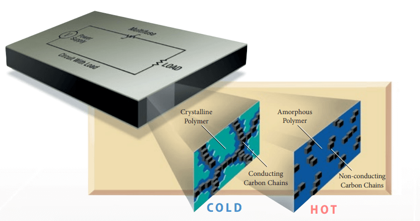
    Resettable fuses work by utilizing a special polymer material that has a positive temperature coefficient of resistance (PTCR).

    The PTCR material in a resettable fuse has a very low resistance at room temperature. When the current flowing through the fuse is within its normal operating range, the resistance of the PTCR material remains low, and the fuse behaves like a normal wire, allowing current to flow freely through the circuit.

    However, if the current flowing through the fuse exceeds a certain threshold, the PTCR material heats up due to the Joule heating effect. As the temperature of the PTCR material increases, its resistance also increases rapidly, causing the current flow to be limited. The PTCR material effectively acts as a self-resetting switch that opens when the current exceeds a certain threshold.

    Once the overcurrent condition is removed and the PTCR material cools down, its resistance decreases, and the fuse returns to its normal operating state, allowing the current to flow again. The resettable fuse can therefore automatically reset itself after an overcurrent event, without requiring any intervention or replacement.

    Key parameters of resettable fuses

    1. Hold current: The maximum current that the fuse can withstand without tripping. The hold current is an important parameter as it determines the maximum continuous operating current of the circuit.
    2. Trip current: The minimum current required to trip the fuse. The trip current is an important parameter as it determines the level of overcurrent protection provided by the fuse.
    3. Maximum voltage: The maximum voltage that the fuse can withstand without breaking down. This parameter is important as it determines the maximum voltage rating of the circuit.
    4. Maximum current: The maximum current that the fuse can handle without causing permanent damage. This parameter is important as it determines the maximum fault current that the circuit can handle.
    5. Time-to-trip: The time it takes for the fuse to trip once the overcurrent condition is detected. This parameter is important as it determines the level of protection provided by the fuse against transient overcurrent events.
    6. Resistance: The resistance of the fuse is an important parameter as it determines the voltage drop across the fuse and affects the efficiency of the circuit.
    7. Operating temperature range: The range of temperatures over which the fuse can operate without affecting its performance. This parameter is important as it determines the suitability of the fuse for use in different environments.
    8. Packaging: The packaging of the fuse is an important parameter as it determines the ease of installation and replacement of the fuse. The packaging options include through-hole, surface mount, and axial lead packages.

    Types of Resettable Fuses

    1. Polymer PTC (PPTC) Fuses: This type of resettable fuse uses a polymer material with a positive temperature coefficient of resistance (PTCR) as the current-limiting element. When the current exceeds a certain threshold, the PTCR material heats up, causing its resistance to increase, which limits the current flow. Polymer PTC fuses are available in various sizes and shapes and can handle currents ranging from a few milliamps to several amps.
    2. Ceramic PTC Fuses: Ceramic PTC fuses use a ceramic material with a PTCR as the current-limiting element. They are commonly used in high-temperature applications because of their high-temperature stability. Ceramic PTC fuses have a low resistance at room temperature and high resistance at elevated temperatures, which makes them suitable for applications where temperature changes can cause overcurrent conditions.

    Advantages and Disadvantages of Resettable Fuses

           Advantages

    1. Automatic Reset: One of the key advantages of resettable fuses is that they can be automatically reset after the overcurrent condition has been removed. As the PTCR material cools down, its resistance decreases, and the fuse returns to its normal operating state, allowing the current to flow again.
    2. Space-saving: Resettable fuses are usually smaller than traditional fuses, which makes them ideal for use in applications where space is limited, such as in portable devices.
    3. Cost-effective: Resettable fuses can be more cost-effective than traditional fuses over the long term because they can be reused after an overcurrent event, rather than having to be replaced like traditional fuses.
    4. Faster response time: Resettable fuses can provide a faster response time to overcurrent events than traditional fuses, which can help protect sensitive electronic components from damage.

           Disadvantages

    1. Limited Protection: Resettable fuses are designed to provide protection against overcurrent events that are within their rated current and time limits. If the overcurrent condition persists beyond the limits of the resettable fuse, the fuse may not be able to protect the circuit and may be damaged.
    2. Temperature Sensitivity: Resettable fuses can be sensitive to temperature changes, which can affect their performance. If the temperature rises beyond a certain point, the fuse may not be able to reset properly, or its resistance may remain high even after the overcurrent condition has been removed.
    3. Voltage Limitations: Resettable fuses may have voltage limitations that restrict their use in high-voltage applications.
    4. Slower Recovery Time: Resettable fuses may have a slower recovery time than traditional fuses, which means that the circuit may not be protected until the fuse has reset.

    Applications of Resettable Fuses

    1. Consumer Electronics: Resettable fuses are commonly used in consumer electronics such as smartphones, tablets, and laptops to protect against overcurrent events that can occur due to faulty charging cables, short circuits, or other issues.
    2. Automotive Electronics: Resettable fuses are used in automotive electronics to protect against overcurrent events that can occur due to faults in the electrical system, such as a short circuit.
    3. Telecommunications: Resettable fuses are used in telecommunications equipment to protect against overcurrent events that can occur due to lightning strikes, power surges, or other issues.
    4. Industrial Control Systems: Resettable fuses are used in industrial control systems to protect against overcurrent events that can occur due to equipment failures, short circuits, or other issues.
    5. Medical Devices: Resettable fuses are used in medical devices to protect against overcurrent events that can occur due to equipment failures, short circuits, or other issues.
    6. Power Supplies: Resettable fuses are used in power supplies to protect against overcurrent events that can occur due to faults in the electrical system, such as a short circuit or overload.
    7. LED Lighting: Resettable fuses are used in LED lighting systems to protect against overcurrent events that can occur due to power surges, faulty wiring, or other issues.

    Resettable Fuses vs. Traditional Fuses

    Resettable fuses and traditional fuses both provide overcurrent protection, but they differ in several ways. Here are some of the key differences between resettable fuses and traditional fuses:

    1. Resetting Capability: The most significant difference between resettable fuses and traditional fuses is that resettable fuses can be reset automatically after an overcurrent event, while traditional fuses cannot. Traditional fuses must be replaced after they have blown.
    2. Response Time: Resettable fuses typically have a faster response time than traditional fuses. This is because the PTCR material used in resettable fuses responds more quickly to changes in temperature than the metal wire used in traditional fuses.
    3. Cost: Resettable fuses can be more expensive than traditional fuses, especially if they are used in large quantities. However, they can be more cost-effective over the long term because they can be reused after an overcurrent event.
    4. Space-saving: Resettable fuses are usually smaller than traditional fuses, which makes them ideal for use in applications where space is limited.
    5. Protection Capability: Resettable fuses have a limited protection capability, while traditional fuses have a more predictable protection capability. Traditional fuses will blow at a specific current level, and the current level is consistent for each fuse. Resettable fuses have a range of current levels at which they will trip, and the current level at which they trip can vary depending on factors such as temperature and previous trip history.
    6. Temperature Sensitivity: Resettable fuses can be sensitive to temperature changes, which can affect their performance. Traditional fuses are less sensitive to temperature changes.

    Tips for Selecting and Using Resettable Fuses

    1. Consider the operating conditions: When selecting resettable fuses, consider the operating conditions of the application, including the voltage and current requirements, the ambient temperature, and the expected operating life of the circuit. Select a resettable fuse that can withstand the operating conditions of the application.
    2. Choose the appropriate resistance value: Resettable fuses have a specified resistance value, which is important to consider when selecting a fuse for your application. Choose a fuse with an appropriate resistance value that will not impact the normal operation of the circuit.
    3. Consider the trip time: Resettable fuses have a trip time, which is the time it takes for the fuse to open when an overcurrent condition is detected. Consider the trip time when selecting a resettable fuse to ensure it is fast enough to protect the circuit.
    4. Proper placement: Proper placement of resettable fuses is important to ensure they provide effective protection. Place the resettable fuse as close to the load as possible, and avoid placing it in areas that are difficult to access.
    5. Avoid exceeding the maximum voltage and current ratings: Resettable fuses have maximum voltage and current ratings, which should not be exceeded. Ensure that the resettable fuse you select is rated for the maximum voltage and current requirements of the circuit.
    6. Test the circuit after tripping: After a resettable fuse has tripped, test the circuit to ensure that it is functioning properly and that there are no underlying issues that caused the overcurrent condition.
    7. Use the manufacturer’s guidelines: Always refer to the manufacturer’s guidelines for proper installation, use, and maintenance of the resettable fuse.

    Future of Resettable Fuses

    The future of resettable fuses looks promising as the demand for electronic devices continues to grow. The increasing use of electronic devices in various industries such as automotive, medical, and consumer electronics is driving the demand for resettable fuses.

    One trend that is likely to shape the future of resettable fuses is the development of smart and connected devices. These devices require advanced circuit protection solutions that can detect and respond to overcurrent conditions quickly and accurately. Resettable fuses with advanced features such as remote monitoring and control capabilities are likely to become more popular in the future.

    Another trend that is likely to impact the future of resettable fuses is the increasing demand for miniaturization. As electronic devices become smaller and more compact, the need for smaller and more efficient circuit protection solutions will increase. Resettable fuses that are smaller in size and offer improved performance and reliability are likely to gain popularity in the future.

    Also ReadTVS Diodes: The Versatile Solution for Circuit Protection

  • TVS Diodes: The Versatile Solution for Circuit Protection

    TVS Diodes: The Versatile Solution for Circuit Protection

    What is TVS diode ?

    TVS (Transient Voltage Suppression) diode is a type of electronic component designed to protect electronic circuits from voltage spikes or transients. Voltage spikes can occur due to a variety of reasons, including lightning strikes, electrostatic discharge, or switching of inductive loads.

    Working of TVS diode ?

    TVS diodes work by responding quickly to voltage spikes or transients that may damage electronic circuits. When a voltage spike occurs, the TVS diode begins to conduct current, providing a low-resistance path to ground. This diverts the excess current away from the protected circuit and limits the voltage to a safe level.

    The TVS diode is designed to have a very high breakdown voltage, which is the voltage at which it starts to conduct current. This allows it to protect against very high voltage spikes, which could otherwise damage the electronic circuit.

    When the voltage spike is over, the TVS diode returns to its high-impedance state, allowing normal operation of the protected circuit. The response time of a TVS diode is typically very fast, on the order of nanoseconds, which ensures that it can respond quickly to voltage spikes.

    Type of TVS diode

    There are two main types of TVS diodes: unidirectional and bidirectional.

    Unidirectional TVS diode

    Unidirectional TVS diodes are designed to protect against voltage spikes in one direction only, typically in the forward direction. These diodes have a single PN junction and are designed to conduct when the voltage across the junction exceeds the breakdown voltage. They are commonly used in applications where the voltage is expected to be unidirectional, such as in power supplies.

    Bidirectional TVS diode

    Bidirectional TVS diodes, on the other hand, are designed to protect against voltage spikes in both directions, both in the forward and reverse directions. These diodes have two PN junctions in parallel, and they can conduct current in either direction when the voltage across either junction exceeds the breakdown voltage. They are commonly used in applications where the voltage can be either polarity, such as in telecommunications and automotive applications.

    Selecting the right TVS diode

     TVS diode for a particular application requires consideration of several factors. Here are some steps to follow when selecting a TVS diode:

    1. Transient voltage level: The TVS diode must have a breakdown voltage (VBR) that is greater than the expected transient voltage level. This ensures that the TVS diode will conduct and limit the transient voltage to a safe level.
    2. Peak pulse current: The TVS diode must have a peak pulse current (Ipp) rating that is greater than the expected peak current of the transient event. This ensures that the TVS diode will be able to handle the current without damage.
    3. Clamping voltage: The clamping voltage (Vc) of the TVS diode should be as low as possible to limit the transient voltage to a safe level. The clamping voltage is the voltage level that the TVS diode limits the transient voltage to.
    4. Response time: The TVS diode should have a fast response time to ensure that it can quickly clamp the transient voltage and protect the circuit. The response time is the time it takes for the TVS diode to start conducting after the transient voltage exceeds the breakdown voltage.
    5. Operating temperature: The TVS diode should be able to operate at the expected temperature range of the application without being damaged.
    6. Package and mounting: The TVS diode package and mounting should be suitable for the application, taking into consideration factors such as board space, lead style, and mounting method.

    Here is the example of SMAJ33A

     The key parameters for the SMAJ33A TVS diode:

    • Breakdown Voltage (VBR): 36.7 – 40.6V
    • Peak Pulse Power Dissipation (PPPM): 400W
    • Peak Pulse Current (IPP): 14.5A
    • Clamping Voltage (VC): 53.3V
    • Reverse Standoff Voltage (VWM): 33V
    • Operating Temperature Range: -55°C to +150°C
    • Package Type: SMA (Surface Mount Axial)

    What are different package of TVS diodes

    TVS diodes are available in various package types to suit different application requirements. Here are some of the most common package types:

    1. Axial package: Axial TVS diodes are cylindrical in shape, with leads at each end. They are typically used in through-hole mounting applications and are available in a range of sizes.
    2. Radial package: Radial TVS diodes are similar in shape to axial diodes, but the leads are located at the base of the cylinder. They are also commonly used in through-hole mounting applications.
    3. SMD (Surface Mount Device) package: SMD TVS diodes are designed for surface-mount applications and are available in various package sizes, such as SOD (Small Outline Diode), SOT (Small Outline Transistor), and DFN (Dual Flat No-Lead).
    4. DO (Diode Outline) package: DO TVS diodes are available in various sizes and are designed for surface-mount and through-hole mounting applications.
    5. Power package: Power TVS diodes are designed for high-power applications and are available in various package types, such as TO-92, TO-220, and TO-247.

    Commonly used TVS diodes series

    Here are some of the most commonly used TVS diodes:

    1. 1.5KE Series: The 1.5KE series is a popular axial TVS diode that is commonly used in protection circuits for automotive, telecommunications, and industrial applications. It has a peak pulse power rating of up to 1.5 kW and a breakdown voltage ranging from 6.8 V to 440 V.
    2. P6KE Series: The P6KE series is another axial TVS diode that is widely used in various applications, including power supplies, telecom equipment, and industrial controls. It has a peak pulse power rating of up to 600 W and a breakdown voltage ranging from 6.8 V to 440 V.
    3. SMBJ Series: The SMBJ series is a popular surface-mount TVS diode that is commonly used in protection circuits for consumer electronics, automotive, and telecom applications. It has a peak pulse power rating of up to 600 W and a breakdown voltage ranging from 5 V to 440 V.
    4. SMCJ Series: The SMCJ series is another surface-mount TVS diode that is widely used in various applications, including power supplies, telecom equipment, and automotive electronics. It has a peak pulse power rating of up to 1.5 kW and a breakdown voltage ranging from 5 V to 440 V.
    5. DFN10-2L Series: The DFN10-2L series is a small surface-mount TVS diode that is commonly used in portable electronics, such as smartphones and tablets. It has a peak pulse power rating of up to 300 W and a breakdown voltage ranging from 3.3 V to 36 V.

    PCB guideline for TVS diode

    When designing a PCB layout for a circuit that uses TVS (Transient Voltage Suppression) diodes, there are some guidelines to keep in mind to ensure effective protection and proper functionality:

    1. Choose the appropriate TVS diode package: Select a package that fits your PCB footprint and can handle the expected voltage and current levels.
    2. Place the TVS diode as close as possible to the protected components: The TVS diode should be placed as close as possible to the input/output pins that need protection to minimize the length of the trace and reduce the risk of voltage overshoot.
    3. Ensure adequate trace width: The traces between the TVS diode and the protected components should be wide enough to handle the expected current levels without causing voltage drop or thermal stress.

    TVS diode equations

    1. Clamping Voltage Equation: The clamping voltage equation for a TVS diode is as follows:

    Vc = VBR + (Ip x Rs)

    Where:

    • Vc is the clamping voltage in volts
    • VBR is the breakdown voltage in volts
    • Ip is the peak pulse current in amperes
    • Rs is the series resistance in ohms
    1. Breakdown Voltage Equation: The breakdown voltage equation for a TVS diode is as follows:

    VBR = K x Vz

    Where:

    • VBR is the breakdown voltage in volts
    • K is the breakdown voltage ratio (typically around 1.5 to 2.5)
    • Vz is the Zener voltage in volts
    1. Zener Voltage Equation: The Zener voltage equation for a TVS diode is as follows:

    Vz = Vf + (Rs x Iz)

    Where:

    • Vz is the Zener voltage in volts
    • Vf is the forward voltage drop in volts
    • Rs is the series resistance in ohms
    • Iz is the Zener current in amperes

    Advantage of TVS diodes

    The main advantage of TVS (Transient Voltage Suppressor) diodes is their ability to protect electronic circuits from overvoltage transients. Here are some of the advantages of using TVS diodes:

    1. Fast response time: TVS diodes have a very fast response time, typically on the order of nanoseconds, which allows them to quickly clamp the transient voltage and protect the circuit.
    2. High surge current capability: TVS diodes are designed to handle high surge currents, which makes them well-suited for protecting against high-energy transient events.
    3. Low clamping voltage: TVS diodes have a low clamping voltage, which means that they limit the transient voltage to a very low level, typically just a few volts above the normal operating voltage of the circuit.
    4. Repeatable performance: TVS diodes have a very repeatable clamping voltage and response time, which ensures that they will provide consistent protection over multiple transient events.
    5. Low leakage current: TVS diodes have a low leakage current, which means they do not draw significant power from the circuit when not in use.

    Disadvantage of TVS diodes

    While TVS (Transient Voltage Suppressor) diodes offer many advantages, there are also some disadvantages to consider. Here are a few potential drawbacks:

    1. Limited lifetime: TVS diodes have a limited lifetime and can be damaged or degraded by repeated transient events. This means that they may need to be replaced periodically in high-transient environments.
    2. Voltage and current limitations: TVS diodes are designed to protect against specific voltage and current levels, and may not be suitable for all applications. It is important to carefully select a TVS diode with appropriate voltage and current ratings for the specific application.
    3. Heat dissipation: TVS diodes can generate heat during transient events, which may need to be dissipated to prevent damage to the TVS diode or surrounding components. This may require additional thermal management considerations in the circuit design.
    4. Reverse bias limitations: TVS diodes are designed to operate in the forward direction, and may not be effective in protecting against reverse voltage transients. Additional protection may be required for reverse voltage transients.
    5. Cost: TVS diodes can be more expensive than other types of voltage protection devices, such as zener diodes or metal oxide varistors (MOVs). However, the cost may be justified in applications where high reliability and fast response times are critical.

    Applications of TVS diodes

    Here are some common applications of TVS diodes:

    1. Protection of electronic circuits in telecommunications equipment, such as modems, routers, and switches.
    2. Protection of power supplies, including AC/DC and DC/DC converters, against voltage surges caused by lightning strikes, electrostatic discharge (ESD), or switching transients.
    3. Protection of automotive electronics against voltage transients and load dump events.
    4. Protection of industrial and automation control systems against electrical noise, power surges, and other voltage transients.
    5. Protection of consumer electronics, such as computers, laptops, and smartphones, against voltage surges and ESD.
    6. Protection of LED lighting systems against transient overvoltage events.
    7. Protection of sensitive electronic components, such as integrated circuits and microprocessors, against voltage surges and electrostatic discharge.
    8. Protection of power transmission and distribution systems against lightning strikes and other voltage transients.

    Conclusion

    In conclusion, TVS (Transient Voltage Suppressor) diodes are an important component in electronic circuits, providing effective protection against transient voltage spikes and surges that can damage or destroy sensitive electronic components. TVS diodes can be used in a wide range of applications, including telecommunications equipment, power supplies, automotive electronics, industrial and automation control systems, consumer electronics, LED lighting systems, and power transmission and distribution systems.

    While TVS diodes offer many advantages, such as fast response times and high reliability, there are also some limitations to consider, such as limited lifetime, voltage and current limitations, heat dissipation, reverse bias limitations, and cost. It is important to carefully consider the suitability of TVS diodes for a specific application and to select a TVS diode with appropriate voltage and current ratings, package type, and other performance characteristics.

    Frequently asked questions

    What is the difference between Zener and TVS diode?

    While both Zener and TVS diodes are used for voltage regulation, Zener diodes are typically used for low-power applications and have a fixed breakdown voltage, while TVS diodes are used for high-power applications and have a nonlinear voltage-current characteristic that allows them to handle transient voltage spikes and surges.

    What causes a TVS diode to fail?

    Here are some common reasons why TVS diodes can fail:

    1. Overvoltage conditions
    2. Excessive power dissipation
    3. Temperature extremes
    4. Reverse bias conditions
    5. Physical damage

    What kind of diode is a TVS?

    A TVS (Transient Voltage Suppression) diode is a type of diode that protects electronic circuits from high voltage transients by clamping the voltage to a safe level. They are designed to react quickly to voltage surges and are commonly used in electronics to protect sensitive components.

    Suggested reads: MOSFETs: The Future of Electronic Switching

  • MOSFETs: The Future of Electronic Switching

    MOSFETs: The Future of Electronic Switching

    Operational amplifiers, or op-amps for short, are widely used electronic components that play a crucial role in many circuits and devices. In this article, we will take a closer look at op-amps, starting with their definition and function, and moving on to explore their many applications, configurations, characteristics, and design considerations.

    Definition and Function

    An operational amplifier is a high-gain voltage amplifier that has two input terminals (one inverting and one non-inverting) and one output terminal. It is typically used to amplify, filter, or process signals in analog circuits. The op-amp is called an “operational” amplifier because it can perform a variety of mathematical operations on its input signals, such as addition, subtraction, differentiation, and integration.

    Applications in Electronics

    Op-amps are used in a wide range of electronic devices and systems, including audio amplifiers, voltage regulators, power supplies, oscillators, filters, comparators, and many others. They are also used in instrumentation and control systems, where their high accuracy and stability are essential.

    Operational Amplifier Configurations

    There are several common configurations of op-amps, including inverting amplifiers, non-inverting amplifiers, summing amplifiers, difference amplifiers, integrators, and differentiators. Each configuration has its own unique characteristics and applications.

    Inverting Amplifier: This configuration amplifies the input signal and produces an inverted output signal. It is widely used in audio amplifiers and other applications where the phase of the signal is not critical.

    Non-Inverting Amplifier: This configuration amplifies the input signal and produces a non-inverted output signal. It is commonly used in applications where the phase of the signal needs to be preserved.

    Summing Amplifier: This configuration adds together multiple input signals and produces a single output signal. It is used in applications such as audio mixers and signal processing.

    Difference Amplifier: This configuration amplifies the difference between two input signals and produces a single output signal. It is used in applications such as instrumentation and control systems.

    Integrator: This configuration produces an output signal that is proportional to the integral of the input signal. It is used in applications such as signal processing and waveform generation.

    Differentiator: This configuration produces an output signal that is proportional to the derivative of the input signal. It is used in applications such as signal processing and waveform analysis.

    Operational Amplifier Characteristics

    Op-amps have several important characteristics that affect their performance and application, including gain and bandwidth, input and output impedance, slew rate, and noise. Understanding these characteristics is essential for choosing and designing op-amp circuits.

    Gain and Bandwidth: Op-amps have a high gain, which is the ratio of output voltage to the input voltage. They also have a limited bandwidth, which is the range of frequencies over which they can amplify signals effectively.

    Input and Output Impedance: Op-amps have a high input impedance, which means that they draw very little current from the input signal source. They also have a low output impedance, which means that they can drive a high load impedance without significant signal loss.

    Slew Rate: Op-amps have a maximum rate at which their output voltage can change, called the slew rate. This limits the maximum frequency of the input signal that can be amplified without distortion.

    Noise: Op-amps have inherent noise that can affect their performance, including thermal noise, shot noise, and flicker noise. Minimizing noise is important for achieving high accuracy and signal-to-noise ratio.

    Choosing the Right Operational Amplifier

    Choosing the right op-amp for a given application depends on several factors, including the supply voltage, precision requirements, power consumption, and signal range. Op-amps are available in many different types and configurations, each with its own set of specifications and performance characteristics. Some of the factors to consider when selecting an op-amp include:

    Single-Supply vs Dual-Supply: Op-amps can operate from either a single power supply or a dual power supply. Single-supply op-amps are typically used in battery-powered devices and low-voltage circuits, while dual-supply op-amps are used in higher-voltage circuits.

    Precision vs General Purpose: Op-amps can be classified as precision or general-purpose, depending on their accuracy and stability. Precision op-amps are used in applications where high accuracy and stability are critical, such as instrumentation and control systems. General-purpose op-amps are used in a wide range of applications where moderate accuracy is sufficient.

    Low-Power vs High-Power: Op-amps can be classified as low-power or high-power, depending on their power consumption and output capability. Low-power op-amps are used in battery-powered devices and low-current circuits, while high-power op-amps are used in high-current circuits and power amplifiers.

    Rail-to-Rail vs Non-Rail-to-Rail: Op-amps can be classified as rail-to-rail or non-rail-to-rail, depending on their output voltage range. Rail-to-rail op-amps can produce output voltages that are very close to the power supply rails, while non-rail-to-rail op-amps have a limited output voltage range.

    Operational Amplifier Circuits and Design

    Op-amps can be used in many different types of circuits and designs, including active filters, oscillators, comparators, and voltage regulators. Understanding the principles of op-amp circuit design is essential for building reliable and effective circuits.

    Active Filters: Active filters are circuits that use op-amps to filter and shape signals. They are widely used in audio amplifiers, equalizers, and other signal-processing applications.

    Oscillators: Oscillators are circuits that use op-amps to generate periodic waveforms. They are used in applications such as signal generators, clocks, and timers.

    Comparators: Comparators are circuits that use op-amps to compare two input signals and produce a digital output signal. They are used in applications such as voltage detectors and threshold detectors.

    Voltage Regulators: Voltage regulators are circuits that use op-amps to regulate the output voltage of a power supply. They are used in applications such as power amplifiers, motor drivers, and LED drivers.

    Troubleshooting Operational Amplifier Circuits

    Op-amp circuits can sometimes experience problems such as oscillation, noise, and distortion. Troubleshooting these problems requires a systematic approach and an understanding of op-amp circuit design principles.

    Common Issues and Solutions: Some of the common issues that can occur in op-amp circuits include instability, noise, distortion, and offset. Understanding the causes of these issues and their solutions is essential for building reliable op-amp circuits.

    Using Simulation Software: Simulation software can be used to simulate op-amp circuits and analyze their performance. This is a powerful tool for designing and troubleshooting op-amp circuits.

    Conclusion: The Importance of Operational Amplifiers in Electronics

    Operational amplifiers are essential components in many electronic circuits and devices. They provide high gain, low noise, and versatile signal processing capabilities that make them ideal for a wide range of applications. Understanding the principles of op-amp design and operation is essential for building reliable and effective circuits.

    Future Trends and Applications

    The use of op-amps is expected to continue to grow in the future, as new applications and technologies emerge. Some of the emerging areas of application for op-amps include wearable electronics, IoT devices, and renewable energy systems. The development of new op-amp technologies, such as low-power and high-speed op-amps, is also expected to drive innovation in the field. As electronic devices become smaller and more power-efficient, the demand for high-performance op-amps will continue to grow. Additionally, the integration of op-amps with other electronic components, such as microcontrollers and sensors, is expected to lead to new and innovative applications in the future. Overall, the future of op-amps in electronics is promising, with continued growth and development expected in the years to come.