What is thyristor ?
A thyristor, also known as a silicon-controlled rectifier (SCR), is a semiconductor device that is widely used in power electronics applications. It is a type of electronic switch that can handle high voltages and currents and is often used in power control circuits.
Constriction of thyristor
Thyristors are made up of four layers of semiconducting material – P-N-P-N – that are sandwiched together to form a single device. The device has three terminals: an anode, a cathode, and a gate. The anode is the positive terminal, the cathode is the negative terminal, and the gate is the control terminal.
Working principle of thyristor
Its working principle is based on the concept of a p-n-p-n structure, which allows it to switch between a conducting and non-conducting state by applying a control signal to the gate terminal.
When a positive voltage is applied to the anode of the thyristor with respect to the cathode, the thyristor remains in the off state, and no current flows through the device. However, if a positive voltage is applied to the gate terminal with respect to the cathode, a small current flows into the gate terminal, triggering the thyristor into the on state.
video Source:youtube
Once triggered, the thyristor remains in the on state even if the gate voltage is removed. The device conducts current until the anode-to-cathode voltage is reduced to zero. At this point, the thyristor turns off and remains off until it is triggered again.
Controlling of thyristor
Thyristors can be controlled by different methods, depending on the specific type of thyristor and the application requirements. The following are some of the most common methods for controlling thyristors
- Gate triggering: This is the most common method of controlling thyristors. By applying a positive gate current, the thyristor can be turned on, and by removing the gate current, the thyristor can be turned off. The gate current is typically very small and does not affect the main circuit.
- Voltage triggering: In this method, the thyristor is turned on by applying a voltage across the anode and cathode terminals that exceeds the device’s breakdown voltage. This method is less common than gate triggering but is still used in some applications.
- Light triggering: This method uses a light pulse to turn on the thyristor. The light pulse is generated by a LED or laser diode, which is directed at a photosensitive region on the thyristor.
- Current triggering: In this method, a pulse of current is used to turn on the thyristor. The current pulse is typically generated by a capacitor discharge or a transformer pulse.
- Phase control: This method is used for AC circuits and involves controlling the phase angle of the AC waveform applied to the thyristor. By controlling the phase angle, the amount of power delivered to the load can be controlled.
Thyristor family devices(Types of thyristor)
There are several types of thyristors, each with its own specific characteristics and applications. Here are some of the most common types of thyristors
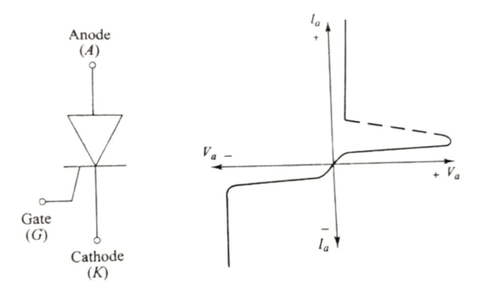
- Silicon Controlled Rectifier (SCR): SCR is the most common type of thyristor and widely used in power control applications. It can be triggered by either voltage or current.
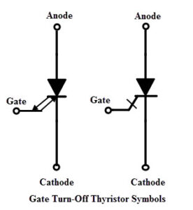
- Gate Turn-Off Thyristor (GTO): GTO is a type of thyristor that can be turned off by applying a negative voltage to the gate terminal. It has a four-layer structure and is used in applications where high switching frequency is required.
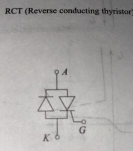
- Reverse Conducting Thyristor (RCT): RCT is a type of thyristor that has an integrated reverse diode. It can be used as a high-speed switch and is commonly used in motor control and power factor correction.
- Light Activated Thyristor (LAC): LAC is a type of thyristor that can be triggered by light. It is used in applications where high speed and high accuracy are required.

Image Source: itwissen - Gate Assisted Turn-Off Thyristor (GATT): GATT is a type of thyristor that can be turned off quickly by applying a voltage to the gate terminal. It is used in applications where high switching speed is required.
- Bidirectional Thyristor (BRT): BRT is a type of thyristor that can conduct current in both directions. It is commonly used in AC switches, motor control, and lighting control.
- Programmable Unijunction Transistor (PUT): PUT is a type of thyristor that has a similar structure to the unijunction transistor. It is used in applications where low power is required.
- Triac: Triac is a type of thyristor that can conduct current in both directions. It is commonly used in AC power control applications.
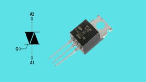
- Diac: Diac is a type of thyristor that can be triggered by a voltage spike. It is commonly used in triggering triacs and other thyristors.
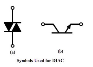
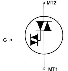
- Quadrac: Quadrac is a type of thyristor that combines the functions of a triac and a diac. It is commonly used in AC power control applications.
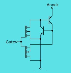
- MOS-Controlled Thyristor (MCT): MCT is a type of thyristor that is controlled by a MOSFET gate. It is commonly used in high-power applications.AC switch: AC switch is a type of thyristor that is used for switching AC power.
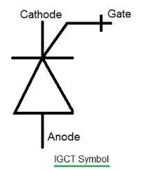
- Integrated gate commutated thyristor (IGCT): IGCT is a type of thyristor that is designed to improve the switching speed and efficiency of power electronic systems.
- Direct Gate-Triggered Thyristor (DGT): DGT is a type of thyristor that is triggered directly by a voltage or current.
- Gate Commutated Thyristor (GCT): GCT is a type of thyristor that is designed for high-power applications and has fast turn-off times.
- Field-Controlled Thyristor(FCT): FCTs are designed to operate at high voltage and current levels and are primarily used in high-power applications, such as inverter drives, motor control circuits, and other power electronics. One of the main advantages of FCTs over conventional thyristors is their faster turn-on and turn-off speeds, which make them suitable for high-frequency switching applications.
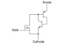
- Static Induction Thyristor(SITH):It is a type of thyristor that combines the features of a MOSFET and a thyristor. it can be turned on and off by a gate voltage, rather than the forward voltage needed to turn on a conventional thyristor. The SITH can be used in high-power applications, such as motor drives, power supplies, and inverters.
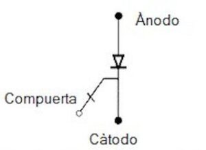
Thyristor applications
Some of the most common applications of thyristors
- Motor Control: Thyristors are commonly used in motor control circuits to control the speed and direction of motors. They can also be used to protect motors from overloading and overvoltage conditions.
- Power Supplies: Thyristors are used in power supply circuits to regulate and control the output voltage and current. They are also used in high-voltage power supplies, such as those used in X-ray machines.
- Lighting Control: Thyristors are used in lighting control circuits, such as dimmer switches, to control the brightness of lights.
- Heating Control: Thyristors are used in heating control circuits to control the amount of power delivered to heating elements. This can be used in applications such as electric stoves, ovens, and industrial furnaces.
- Power Factor Correction: Thyristors are used in power factor correction circuits to improve the efficiency of power delivery in AC circuits.
- Inverters: Thyristors are used in inverter circuits to convert DC power into AC power. This is commonly used in solar power systems, where DC power from solar panels is converted into AC power for use in homes and businesses.
- Battery Charging: Thyristors are used in battery charging circuits to regulate the charging current and prevent overcharging of batteries.
- Electronic Switching: Thyristors are used in electronic switching circuits to control the flow of current in electronic circuits.
Thyristor selection key factors
When selecting a thyristor for a specific application, there are several criteria that need to be considered. Here are some of the key factors to consider when selecting a thyristor
- Voltage Rating: The voltage rating of the thyristor should be chosen to match the voltage of the application. The voltage rating of the thyristor should be higher than the maximum voltage of the application to ensure safe operation.
- Current Rating: The current rating of the thyristor should be chosen to match the current of the application. The current rating of the thyristor should be higher than the maximum current of the application to ensure safe operation.
- Turn-on Time: The turn-on time of the thyristor is an important factor to consider, as it affects the switching speed of the device. In applications where fast switching is required, a thyristor with a shorter turn-on time should be selected.
- Turn-off Time: The turn-off time of the thyristor is also an important factor to consider, as it affects the recovery time of the device. In applications where fast recovery is required, a thyristor with a shorter turn-off time should be selected.
- Operating Temperature: The operating temperature of the thyristor is an important factor to consider, as it affects the reliability and lifespan of the device. In high-temperature applications, a thyristor with a higher temperature rating should be selected.
- Gate Trigger Current: The gate trigger current of the thyristor is an important factor to consider, as it affects the gate drive requirements of the device. In applications where low gate drive requirements are desired, a thyristor with a lower gate trigger current should be selected.
Formula related to thyristor
There are several formulas related to thyristors that are commonly used in electronic circuits and power systems. Here are some of the important formulas related to thyristors:
- Holding Current (IH): This is the minimum current required to maintain the thyristor in the conducting state. The formula for holding current is given by:
IH = α IT
where α is the anode current gain and IT is the latching current.
- Latching Current (IL): This is the minimum current required to trigger the thyristor into the conducting state. The formula for latching current is given by:
IL = (η/β) IT
where η is the turn-on efficiency and β is the holding current gain.
- Peak Reverse Voltage (PRV): This is the maximum reverse voltage that can be applied to the thyristor without causing breakdown. The formula for peak reverse voltage is given by:
PRV = VDRM + VRRM
where VDRM is the maximum repetitive off-state voltage and VRRM is the maximum non- repetitive off-state voltage.
- Turn-On Time (ton): This is the time taken for the thyristor to switch from the off-state to the on-state. The formula for turn-on time is given by:
ton = (π/2) (RT x CT + VGT / IG)
where RT is the external resistance, CT is the external capacitance, VGT is the gate trigger voltage and IG is the gate trigger current.
- Turn-Off Time (toff): This is the time taken for the thyristor to switch from the on-state to the off-state. The formula for turn-off time is given by:
toff = (π/2) (RT x CT + VBO / IH)
where VBO is the blocking voltage and IH is the holding current.
These formulas can be used to calculate various parameters related to thyristors and help in designing and analyzing electronic circuits and power systems.
Advantages of thyristor
Thyristors have several advantages that make them popular in a wide range of electronic and power system applications. Some of the advantages of thyristors are
- High current and voltage handling capability: Thyristors can handle high current and voltage levels, making them suitable for high power applications such as motor control and power supplies.
- Fast switching speed: Thyristors can switch on and off quickly, which is important in applications where precise control of power and voltage is required.
- High reliability: Thyristors are highly reliable and can operate for long periods without failure, making them ideal for applications that require continuous operation.
- Low cost: Thyristors are relatively low cost compared to other power switching devices, making them a cost-effective solution for many applications.
- Simple control circuitry: Thyristors have a simple control circuitry, which makes them easy to integrate into electronic circuits and power systems.
- High efficiency: Thyristors have high efficiency and low power dissipation, which reduces the amount of heat generated during operation and helps to increase the overall efficiency of the system.
- Ability to handle AC and DC power: Thyristors can handle both AC and DC power, making them suitable for a wide range of applications such as power supplies, motor control, and voltage regulation.
Disadvantage of thyristor
While thyristors have many advantages, they also have some disadvantages that should be considered when selecting a power switching device for a specific application. Here are some of the disadvantages of thyristors:
- Limited controllability: Once a thyristor is turned on, it cannot be turned off until the current through the device drops below the holding current. This lack of controllability can make it difficult to use thyristors in applications that require precise control of power and voltage.
- Limited frequency range: Thyristors have a limited frequency range and may not be suitable for applications that require high frequency switching.
- Limited protection against overvoltage: Thyristors may be vulnerable to overvoltage conditions, which can damage the device or cause it to fail. Proper protection circuitry should be used to prevent overvoltage conditions.
- Limited protection against overcurrent: Thyristors may be vulnerable to overcurrent conditions, which can cause the device to fail or become damaged. Proper protection circuitry should be used to prevent overcurrent conditions.
- Voltage drop: Thyristors have a voltage drop across the device when conducting, which can cause power losses and reduce the overall efficiency of the system.
- Thermal management: Thyristors generate heat during operation and require proper thermal management to prevent overheating and damage to the device.
Packages of thyristor
Thyristors are available in various package types depending on their application and power rating. Here are some of the common package types for thyristors:
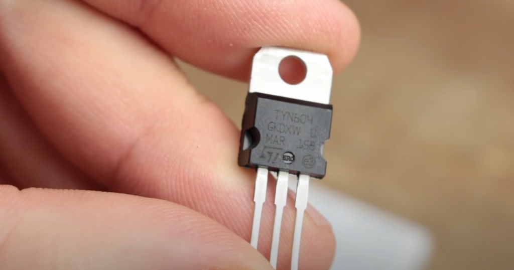
- TO-220: This is a popular package for low to medium power thyristors. It has a metal tab for heat dissipation and three leads for the anode, cathode, and gate connections.
- TO-247: This package is similar to the TO-220 package but is larger and has a higher power rating. It has a metal tab for heat dissipation and three leads for the anode, cathode, and gate connections.
- SOT-223: This is a surface mount package for low to medium power thyristors. It has four leads for the anode, cathode, gate, and heat sink connections.
- D2PAK: This is a surface mount package for high power thyristors. It has four leads for the anode, cathode, gate, and heat sink connections.
- Module: Thyristors are also available in module packages that have multiple thyristors and other components on a single package. These packages are commonly used in high power applications such as motor control and power supplies.
In conclusion
Thyristors are essential electronic devices used for power control applications. They provide a reliable and efficient means of regulating power flow in circuits, making them ideal for use in various industrial and commercial applications. Thyristors are available in various types, such as SCR, TRIAC, GTO, and others, each with its unique characteristics and advantages.
The working principle of thyristors is based on the control of minority carrier injection, which is influenced by the gate signal. By controlling the gate signal, the thyristor can be turned on and off at will, allowing for precise control of power flow in the circuit.
While thyristors have many advantages, such as high power handling capabilities, efficient operation, and long life, they also have some limitations, such as their relatively slow switching speeds and the need for a minimum holding current to maintain their on-state.
Overall, thyristors continue to be widely used in power control applications, and advancements in their technology continue to improve their performance and efficiency.
Frequently ask question
What is the difference between a thyristor and an IGBT?
While both IGBT and thyristors are power electronic devices used for switching and amplification of electrical power, they differ in their internal structure and mode of operation.
IGBT is a three-terminal device that combines the features of both MOSFET and bipolar junction transistor (BJT), whereas thyristor is a four-layer PNPN semiconductor device. IGBT is a voltage-controlled device, whereas thyristor is a current-controlled device.
One significant advantage of IGBT over thyristors is that IGBTs can be turned off by removing the voltage applied to the gate, whereas thyristors require a current reversal to turn off. This makes IGBTs more suitable for high-frequency switching applications.
How do you test and troubleshoot thyristors?
Use a multimeter: Set the multimeter to the diode test mode and connect the positive probe to the anode and the negative probe to the cathode. If the thyristor is functioning properly, the multimeter should show a voltage drop across the anode and cathode.
Why SCR is called thyristor?
SCR stands for Silicon Controlled Rectifier, which is a type of thyristor. The term “thyristor” refers to a class of semiconductor devices that have four layers of alternating P-type and N-type material. The name “thyristor” is derived from the Greek word “thyra,” meaning “door,” which refers to the device’s ability to control the flow of electric current like a switch. Therefore, an SCR is called a thyristor because it is a specific type of semiconductor device that falls under the thyristor category.
What are the 3 states of SCR?
- Forward-blocking state: In this state, the anode of the SCR is positive with respect to the cathode, but no current flows through the device because the gate is not triggered.
- Forward-conduction state: In this state, the anode is still positive with respect to the cathode, but current is flowing through the device because the gate has been triggered.
- Reverse-blocking state: In this state, the cathode is positive with respect to the anode. In this state, the SCR blocks current flow in both directions.
Also Read: BJT: The Versatile Transistor for Electronic Design
